 » FEA Knowledgebase » FEA Analysis » Need of 3D CAD models and FEA for Mechanical Components Prior to Fabrication
Need of 3D CAD models and FEA for Mechanical Components Prior to Fabrication
Posted by Rohan Belhe on January 16th, 2017
Gone are the days when research and development engineers, design engineers and manufacturers used to fabricate a component and test it against physical testing methods with destructive testing approaches. Mostly all the components undergo structural model based analysis approach using software like ANSYS or calculative analysis approach to check the design strength and safety. Ideally, any component that is designed passes through several processes of calculation, checks, compatibility, tests, and analysis for various purposes before being fabricated. However, there are two major processes involved that has a huge impact on the overall product development.
Generating 3D CAD Models
Drafters generate 2D design sketches which are then handed over to the professional CAD drafters for creation of 3D CAD model. Once the model is generated, it is rendered for further coordination with the manufacturing engineers and stakeholders to understand its projected set of requirements. Confined boundaries, enhanced surfaced and accurate dimensions give a pleasing and easy to perceive look to the model and can be understood well without requiring much of imagination skills. With this, the changes as asked can be made and designs are finalized.
Analysis of 3D CAD Models
After the finalization of designs, these 3D models are further subjected to verification of safety measures by studying the behavior of the product under various conditions. Predictions of failures, heat generation and transfer, vibration analysis, fatigue analysis etc., are some tests to optimize the product design and help the engineers to take critical decisions. For validation of safe design, boundary conditions and convergence analysis are performed as well. Several numerical and mathematical calculations and model based tests are also involved before the confirmation of design safety. By analysis, the idea related to sustainability and maintenance of the product is crystal clear.
The analysis done is classified into static and dynamic equilibrium conditions depending upon the component to be designed and analyzed. Some designers also provide linear static analysis for products going under linear deformation, small deflection and other changes under yield point of the product material. While on the other hand, non-linear static analysis is done for large deformation that includes examination of the product right from initial zero loading conditions and no stress to non-linear stress generation, caused by loading to see if the product leads to failure.
Why go through all this?
If design alterations are made during the product development stage, lot of rework can be spared and it gives a better way to launch the product in the market at the right time. Besides, these processes help in reducing the manufacturing time, since the designs are already validated for fabrication processes and thereby process planning can be done quickly. The analyses results help understand the behavior of stresses generated in the component under small values of stress.
Case study
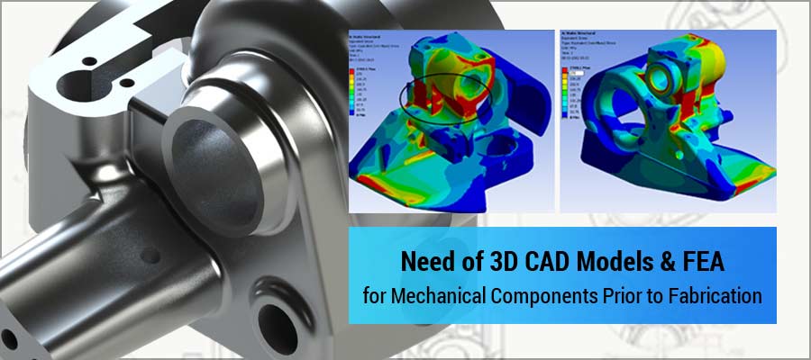
Engineers at Hi-Tech performed Finite Element Analysis for structural assembly of fifth wheel for heavy transport engineering in Australia. Entire assembly as well as each individual component of the frame was analyzed by load application to check the design safety. Upon analysis, it was observed that the stress values exceeded the safety design limits, pointing a change in design to avoid the failure.
Conclusion
Thus, the pre-fabrication processes that a component undergoes are needed in order to avoid pre-mature failure of the component and ensure design safety. Since manufacturers, fabricators and design engineers have the responsibility of developing a safe and sustainable product, checking the design before its fabrication is and should be an integral part of the product development.
About Author : Rohan Belhe FEA specialist at Hi-Tech, is an expert at ANSYS APDL, ANSYS Mechanical, Simulia Abaqus & Hyperworks. With more than 5 years of experience, Rohan has planned, coordinated and executed projects for off-highway vehicles, heavy machineries, engine & transmission, automotive & ancillaries, process equipment's and pressure vessels. Rohan adept at co-ordination and QA/QC, handles a team of FEA engineers engaged in delivering accurate, timely and cost-effective solutions for building products & components design, fabricated metal & alloy product design, machinery design and medical devices.
